For quite a few years, I've been unsuccessfully trying to wrap my head around this particular portion of Revit. All sorts of experts came up with explanations, processes, and best-practices to tackle the issue. All of the explanations seem like the picture below to me:
 |
Fig 1: Blind men trying to comprehend an elephant. From Wikipedia. Read the Story here.
This is not an allegory for the folks who have written about this topic. It is a metaphor for my (and a lot of my colleagues') difficulty in comprehending the topic based on their writing. |
For anyone transitioning from an AutoCAD workflow to a Revit one, it is often a given that one would instinctively take the a laissez faire approach to handling the issue of setting out Origin Points for a project. Revit as an application, is fairly good at downplaying the whole issue. It usually does not matter until one has to link other models into the Main model where all the documentation is being recorded. Even then, someone in the team magically figures out how to use Shared Coordinates and make the linking work. Then someone accidentally removes a link, or overwrites a Shared Coordinate and then this whole setup suddenly fails to make sense anymore. It is often worse when, later in the project, one has to aggregate all the models in simulation platforms such as Navisworks or Synchro due to the simple reason that other programs are usually unable to read Revit's Shared Coordinates or the teams do not export projects consistently. One can certainly ensure that the project is exported using Shared Coordinates. In practice however, I've found that there are always one or two models that somehow slip between the cracks. So, the work-around seems to be one where one imports all the models, then painfully find objects that belong to the same coordinates and then align everything. Life would be a lot easier, if someone had set the ground rules from early on in the project.
Number of Origin Points
Different experts have proposed differing hypothesis on how may different kinds of origins Revit has. After having my head spin around the different narratives for a while, I realized that the number of Origins depends on how one counts them.
 |
| Fig 2: The Project Base Point (Left) and the Survey Point (right) visible (typically hidden in most views) in the Revit Project |
As with all modeling/drafting applications, the Revit Space can be imagined as being set on an infinite grid in 3D space. For lack of a better descriptor, lets call this the World Coordinate System (WCS). The Project Base Point (PBP) and Survey Point (SP) are attached to separate grids that are overlaid on the first Grid. As indicated earlier, the markers(the default location of the marker is the grid point 0,0, but that need not be the case always) are indicated by the symbols above. The rub however, is that there is no marker for the 0,0 of the Relative Origin (RO) or the Origin of the WCS... It is a Ghost!
 |
| Fig 3: The Relative Origin (never seen) in every Revit Project. This is the equivalent of the 0,0 of World Coordinate System (WCS) in AutoCAD. Sadly, locating this point is often a tedious process once the Project Base Point and the Survey Points have been moved off their original locations and the project rotated.
|
The two symbols in Fig 2 represent the two visible Base Points within every Revit Project: The Project Base Point (PBP) and the Survey Point (SP). It would do well for us to remember that these two points are really not immutable 'origin' points, but markers to mark the location of a known point within their respective systems or Grids. The previous sentence sounds just as confusing to me as any of the other narratives one may have read about Revit Origin Points elsewhere. So I'm going to attempt to elaborate on this with images...
 |
| Fig 4: For the sake of clarity, I pulled the Project Grid and the Survey Grid 10' above and below the WCS respectively. The image shows the PBP and the SP at their respective origin points relative to their corresponding grids. We will talk about the incongruities in the reported coordinates of the PBP and SP in a bit (We'll also talk about the giant paper clip in there I promise) Note: The location of the WCS marker will move with the PBP in this scenario. One will have to relocate the marker physically to the correct location. (0,0 of the WCS or the Relative Origin) Note that when the PBP was moved up (while clipped), the whole Project and Grid moved with it as well. The same is true for the Survey Grid except that it moves relative to the Project Grid and World. In many ways this image is misleading: When the PBP is moved while clipped, it is actually clipped to the World. So it wouldn't actually move up independent of the World as suggested in the image above - but I'm going to wave my hand at it for now because it helps me see things better. |
The most important take away from this image is that if we move the PBP (while it is clipped), we are actually moving the project (and all its elements except the Survey Point) relative to the WCS of the Project. Why is this a problem? Well, if the structural engineer placed his or her columns before you moved the PBP, now the Link containing the Structural Model will land in the wrong Z location (in this case) when linking Origin-To-Origin. A tit-bit for myself: 'Origin-To-Origin' really means '
Relative Origin-to-Relative Origin'. This may not be a big deal in a simple scenario such as this, but in a complex project with a rotation applied to Project North, this can be nearly impossible to fix. So what happens when one moves the PBP marker after unclipping the paperclip? Let's take a look...
 |
| Fig 5: When the PBP is moved after the paper clip is un-clipped, the reported location of the PBP is still what you would expect relative to the WCS. However this time, only the Project Grid Moves. Note that the Project (Building) did not move when the PBP was moved while Un-clipped. The Red Slash across the Paper Clip indicated un-clipping. |
Moving the PBP while un-clipped lets one change the location of the Project Grid. What does this really mean in practice? Think about how column coordinates are reported...
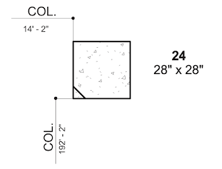 |
| Fig 6: Typical Column Coordinates for Construction Documentation |
The typical column coordinates is reported in the Project X and Project Y directions from a Working Point that is usually placed at a known point on the site. Many times this Working Point is not determined until after the project has been set up. In most cases, the Project X and Project Y directions are completely different from the Real world North/East Coordinates. Thus un-clipping the PBP and moving it to the designated Working Point, is an easy way to change the reported X and Y coordinates of all elements within the project without actually moving the project. Un-clipping also ensures that the Relative Origin (WCS) is always known which in turn means all the linking and import/insert will work without the need for Shared Coordinates (a simple 'Origin-to-Origin' positioning would suffice).
Example Project Setup
Here is a test project setup to test all of our previous assumptions. Another reason to set up a project is to derive a process for setting up Base Points for all projects in a firm.
 |
| Fig 7: Sample Project setup showing Relative Point Coordinates (R-prefix, red color), Project Base Point Coordinates (P-prefix, green color), and Survey Point Coordinates (S-prefix, brown color). The Relative Point (WCS) is identified by a custom Marker, while the PBP and SP has a built in marker. |
The Survey Point was moved while clipped whereas the Project Base Point was moved while un-clipped - Similar to the translation in Fig 5. The implications of these actions are discussed in-depth in the
Autodesk Help Document . According to this documentation, moving the Survey Point while clipped essentially changes the Survey Coordinates on all building elements. Moving the Survey Point while un-clipped, leaves everything unchanged except for the coordinates of the Survey Point itself which now reads its distance from its original location (some experts call this the Survey Origin).
 |
| Fig 8: Sample Setup in the Vertical Axis. Here the Project Base Point or the Working Point of the project is 2'-0" above the Relative Point (WCS). The Survey Point is located at the Survey Datum provided by the project surveyor. |
In this project, the Base Plane Level is the level type indicating the elevation above the Survey Point (Project Survey Datum) while Level 1 reads the elevation above the Project Base Point. All the building levels are listed from Level 1 onward. The Relative Origin (WCS) is always known because of the marker element placed there by the user. The PBP is always updated by un-clipping and moving it vertically to the Base Plane Level if the Base Plane Level were to change.
Rotating Project North
 |
| Fig 9: Plan view of the Project as shown in Fig 7 now rotated by 30 degree (counter clockwise) from True North about the Relative Origin (WCS) |
After rotation of True North (this is done about the Relative Origin), the coordinate points are all seemingly awry. This is because the rotation of all the survey coordinates about the Relative Origin. The formula to calculate the new coordinates of a point rotated about an origin is:
X = x Cosθ + y Sinθ
Y = y Cosθ - x Sinθ
There is a handy calculator that you can use to do the math
here. So, in order to verify our hypothesis, I've overlaid the before and after rotation images to work out the math for the new coordinate values.
 |
| Fig 9a: Overlay of Coordinates with the before rotation state in the background (mustard) |
One interesting tit bit I discovered during the course of this exercise is that although one would expect the 'X' in the formula to correspond with the East-West Coordinate and the 'Y' with the North-South, it turns out that the order is reversed in Revit.
West to East= x Cosθ + y Sinθ
South to North = y Cosθ - x Sinθ
For example, if one were to rationalize the Shared Coordinate values for the rotated Project Base Point (the Working Point for this project), it would look like the diagram below:
 |
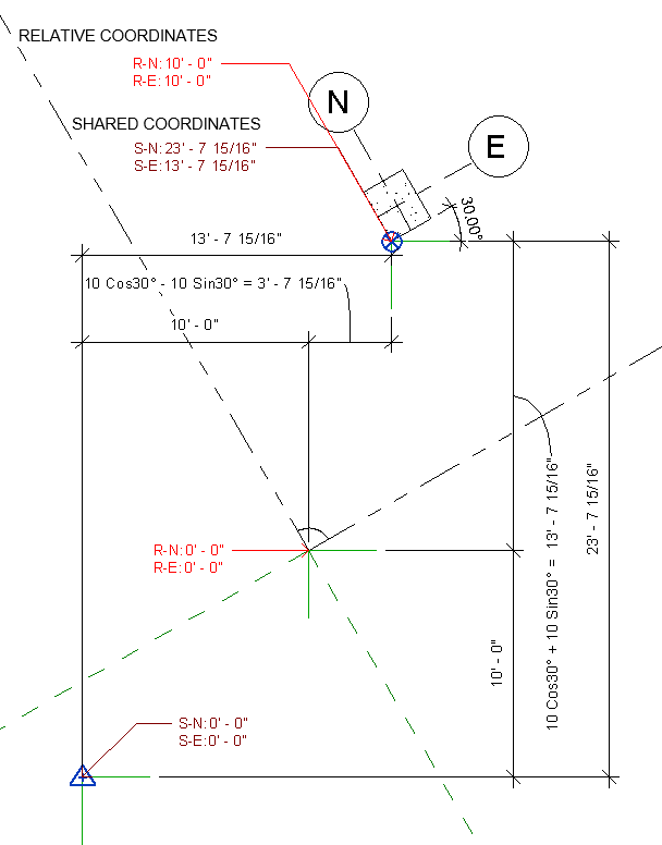
| Fig 10: Rationalization of the Shared Coordinates for the Project Base Point after a 30° (Counter Clockwise) rotation about the Relative Origin (WCS) of the project. |
One feature of note in this arrangement is that although the project has been rotated,
the Survey(Shared) Coordinate System is always orthogonal to the screen. In other words, the Survey Grid and the Relative Grid (World) are always parallel to each other. Hence when the project is rotated, the rotated coordinates are calculated as the sum of the distance to the Relative Origin and the rotated distance from the Relative Origin to the actual point for which the coordinates are being reported.
Specify (Shared) Coordinates At a Point
Maybe it was an exercise in brevity, but it is not until one sees the dialog box associated with the tool does one realize that this is for specifying Survey(Shared) Coordinates for a picked point. In the example below, I've set the Shared Coordinate for the Working Point (PBP) of this project at 30, 30. This action in effect moves the Survey Point to a location 30 feet South and 30 feet East of the Working Point.
 |
| Fig 11: Specifying Shared Coordinates at a Point moves the Survey Point to the location where a Survey Datum may exist. The same task can be accomplished graphically by simply dragging the Survey Point to the correct location on plan. |
In other works, the positive Shared Coordinates represent the distance of the Survey Point South and East of the point being specified.
Publish/Acquire Coordinates:
My biggest challenge in understanding this particular tool is its seeming incongruity. It is one of those things where one understands what it does conceptually, but the results can be unexpected at times. So its time for step-by-step pictures...
 |
| Fig 12: The Building Project: I'm starting with a simple project with four walls. The Project Base Point, Survey Point, and the Relative Origin are all located in the same location. |
 |
| Fig 13: The Site Project: Using the 'Insert Link' tool, the project is brought into the test 'Site' project we were working with earlier. The insertion is 'Origin-to-Origin' and the link automatically assumes the rotation of the Site project. Being 'Origin-to-Origin', the Relative Origin (WCS) of the link matches up with the Relative Origin of the Site. |
 |
| Fig 14: Using the Move tool, the link is moved to the correct location at the Working Point of the Site Project. |
Using the 'Publish Coordinates' tool, one can push the relation between the Survey Point and the Relative Origin into the Linked File as a Project Position.
 |
| Fig 15: Publishing causes the relationship between the Relative Origin and the Survey Point to be recorded in the linked file. In the example above, this relationship from the Site project overwrites the existing relationship in the linked file when the Internal(current) Project Position is overwritten. |
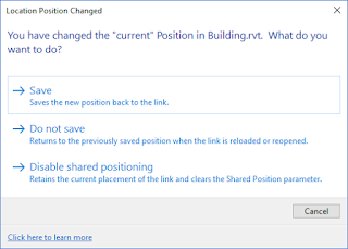 |
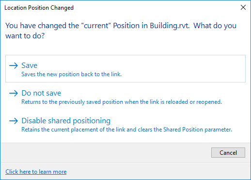
| Fig 16: When the Site Project is saved, the user is asked if he or she wants to save the Current Position of the Link |
When a new position is saved, one is actually modifying the linked file without opening it. This is tricky when dealing with models that are submitted by consultants. Typically, consultants submit a model and then submit updated models periodically. Unless this change of position is recorded and sent back to a consultant for him or her to continue working on, any updates will not have the Shared Positioning. This particular realization (or the lack thereof) has been the cause of many a headache in inter-office projects.
Inside the Link
So we have published the coordinates of the Site model into the building model. Let's take a look at what happens inside the link:
 |
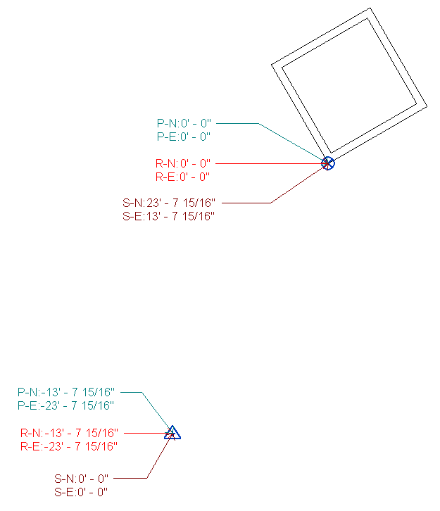
| Fig 17: Positions of the Survey Point and Relative Origin within the Building Model mirror that of the Site Model. Note that the rotation of the Project Grid is transferred as well. |
As you can see, the positions of the Relative Origin and the Survey Point mirror the Site model. Interestingly, the Project Base Point is not mirrored. This is because, the PBP always needs to to be local to the building model. Remember that the PBP is used as the Working Point (Origin) of the Building for documentation purposes.
 |
| Fig 18: The Project Base Point (PBP) is used as the Working Point (Origin) of the Building Project. Hence it can be un-clipped and moved to any convenient location . The Project Coordinates annotation always reads the relative position of the PBP. |
Acquire Coordinates
The Acquire Coordinates tool transfers the Shared Sites settings in the direction opposite to the 'Publish' tool. In this case, one can insert the Site Link into the Building model, position the Site in the correct position relative to the building and then 'acquire' the relation between the Site model's Relative Origin and Survey Point (Origin of Survey Grid \ Shared Coordinate System).
Shared Sites / Project Position
The position of the Relative Origin and the Survey Points are recorded in a setting named Shared Sites or Project Position. A project can have any number of Positions, but each project has to have at least one Position. The default Position is called 'Internal'. When a project is launched using the default templates, the Relative Origin and the Survey Point are in the same location.
So when will a project have multiple Positions?
Let's take an example of a number of buildings (indicated by four wals each) replicated on a site model (it could also be a number of floors replicated in a building). In this scenario, the building is modeled in a Building.rvt model and the site lives in its own model.
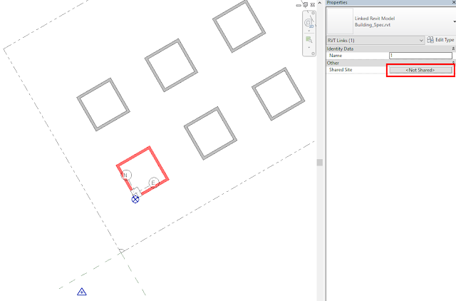 |
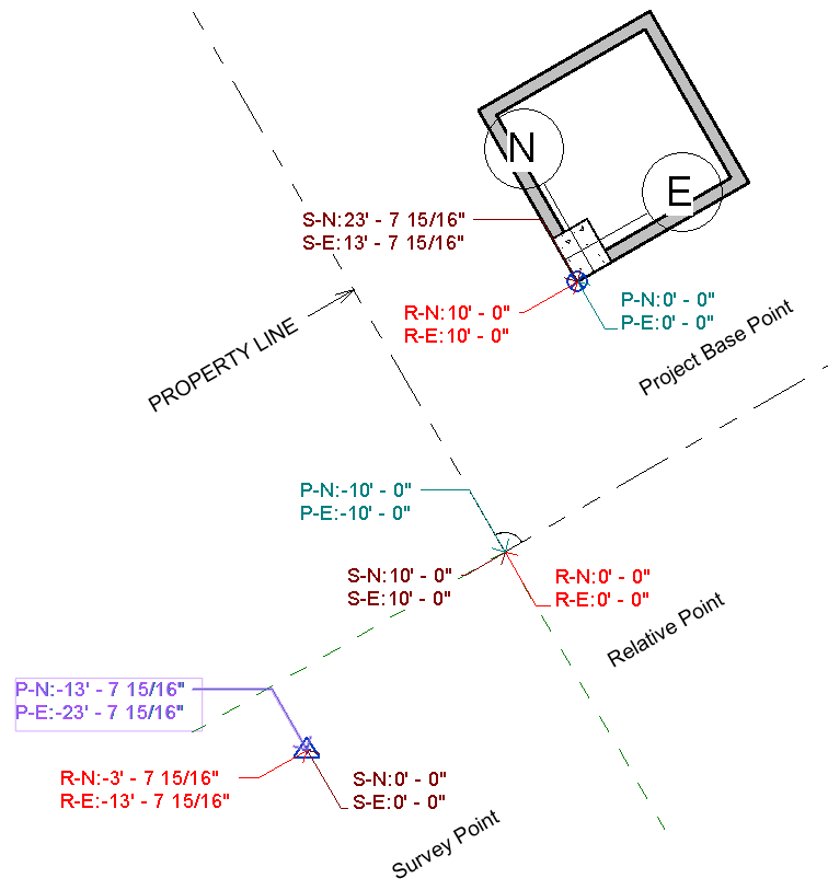
| Fig 19: Six replications of a single building model link within the site model. Note that the Shared Site property of the link indicates that the host and linked projects don't have a Shared Coordinate System. What this means is that the linked model does not remember the location of the model vis-a-vis its Survey Point for each of these six positions. |
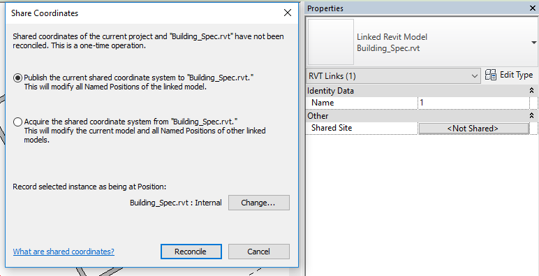
In order to share the position of the Survey Point of the Site Model with the Relative Origin of the linked Building Model, one has to set the Shared Site Parameter for each of the linked instances of the building model. This can be done by clicking on the '<Not Shared>' button.
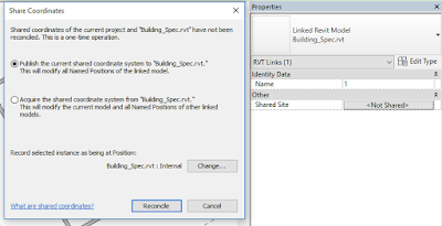 |
| Fig 20: Sharing a site between the host and the link |
Sharing can happen two ways: by publishing or acquiring. Each of these modes indicate the direction of sharing. In our particular case, we want the Survey Point-Relative Origin relationship from the site model to be recorded in the building model for each of the link's locations. Hence we need to 'Publish' the current relationship. The problem with Revit's default Acquire/Publish tools is that it overwrites the current setting whatever it might be. In order to create new Project Locations/Shared Sites, we need to look at the lower end of this dialog, Revit tells us that the Publish/Acquire action will overwrite the 'Internal' named position/Shared site of the link. There is inherently nothing wrong with this action but we have to record six positions for each of the locations where the link was placed.
 |
| Fig N: Creating new Shared Sites in the Linked Model |
 |
| Fig 21: Duplicating and renaming the Internal Site of the linked building model. |
 |
| Fig 22: The previous process is repeated for all six copies of the link. Note the '(in use)' notification next to the Position name |
This process, in essence is the process of creating Shared Coordinates - as in, we are recording the position of the Survey Grid for each position of the building link on the site. If the link were ever removed from the project, the link can be reinserted into the project by using the 'By Shared Coordinates' option in the Insert Dialog box and Revit will ask us which Shared Site we would like to place the building. What if one of the copies of the link were deleted? No problem! simply make another copy and then select its 'Shared Site' parameter and choose the appropriate Shared Site / Project Position.
 |
| Fig 23: Moving a copy of a link to one of the recorded Shared Site within the link |
Summary (from various resources):
Having muddled through most of the features of Revit's coordinate system, I hope to separate the conceptual underpinnings of the tool-set from the interface itself. In retrospect, I believe that the Coordinate System of Revit is fairly simple and logical. However, the design of the interface and the lack of transparency of the operations make this a very challenging feature to many users. So here is a summary of all the pieces of information gathered from various sources:
- Revit has three coordinate grids:
- The World (or World Coordinate System a-la AutoCAD). The Relative Origin is the 0,0 of this grid and there is no marker to indicate this position within Revit.
- The Shared Coordinate System or the Survey Grid as I called it earlier with the Survey Point as the visual indicator of it origin.
- The Project Coordinate System or the Project Grid with the Project Base Point as the visual indicator of its origin. All model elements anchor to this grid. Moving or rotating this grid does the same to the model/project.
- The Shared Coordinate System (Survey Grid) and the WCS are always parallel.
- When the project is Rotated, the Project Grid is rotated relative to both the World (WCS) and as a result the Survey Grid (Shared Coordinate System)
- Project Position or Shared Site represents the relationship between the Shared Coordinate System and the World (WCS). Graphically speaking, this is represented by the position of the Survey Point relative to the Relative Origin.
- Every Revit Project has a default Project Position or Shared Site known as 'Internal'. Additional Shared Sites may be created if the project is linked into another project and duplicated within that project at multiple coordinate locations.
- Publishing coordinates to a linked model transfers the Survey Point Origin (Shared Coordinate Origin) - Relative Origin relationship of the host model to the current Shared Site within the linked model. Acquiring does the opposite.
- Moving the Project Base Point while clipped actually moves the Shared Coordinate System (Survey Grid) in the opposite direction. In other words, this is the same as re-positioning the project relative to the Survey Point. In effect, this changes the Shared Coordinates of the model (and is fairly dangerous to do within a model with links)
- Moving the Project Base Point while un-clipped, moves only the Project Grid Relative to the Relative Origin. This feature can be used to position the Working Point of projects anywhere within the project as all of the Annotation reading Project Coordinates will reference the distance from this point. This action will not have any impact on the Shared Coordinate System and hence will not affect links.
- Moving the Survey Point while clipped changes its relationship with the World and hence is actually akin to moving the project. However, unlike the situation similar to moving the Project Base Point while clipped, the whole project will not appear to move in the view window because we are basically changing the relationship of the Shared Coordinate System to the World. In other words, we are changing the Project Location/Shared Site and the only change one will notice in the project views will be the update of all annotations displaying the Survey / Shared Coordinates.
- Moving the Survey Point while un-clipped has no effect on anything as this just moves the Survey Point relative to the Survey Grid (Shared Coordinate System). It has no effect on annotation calling out the Survey Coordinates because these annotations (unlike Project Coordinates) always read the 0,0 of the Survey Grid rather than the location of the Survey Point.
Good Practices to keep one's sanity around the Coordinate System
- I find it preferable to avoid using Shared Coordinates altogether when possible. In fact it is only necessary when a link is replicated in multiple locations within a project. Steve Strafford points this out in his generalizations here.
- Eschewing Shared Coordinates requires that all model authors in a project to agree on the location of the Relative Origin. The Survey Point can be moved using the move tools to the Site Datum in each of the linked models. Alternatively, Acquire/Publish may be used to overwrite the 'Internal' Project Position of each link after first ensuring that the Relative Origins match. Although one is technically sharing coordinates in this scenario, one can still re-link models using the 'Origin-to-Origin' method. The moving of the Survey Point is required only in those models that need to call out the Survey Coordinates. For example, the Architectural and the Structural model need to call out the positions of various elements relative to the survey datum and hence are candidates for making sure that the Survey Point is in the right location.
- As insurance if anything were to go wrong, each model/link should have a model marker indicating the position of the Relative Origin. This not only allows one to detect any errors should they occur, but also serve as a way to align models in Revit and beyond should the models become misaligned or if the Project Position/Shared Site is (accidentally) overwritten.
- I would generally avoid the use of the Publish/Acquire Tools from the ribbon. This is because using these tools overwrites the existing Shared Site/Project Location. It does not give the user a choice to duplicate the existing Project Location and record the new Location separately. In my experience, this has led to many accidental overwrites of the Project Location causing headaches for the team later on. I am convinced that the process described in the Shared Sites / Project Location section of this blog is safer.
 |
| Fig 24: Sample Origin marker family |
All comments, corrections, and queries welcome :)


No comments :
Post a Comment